
Views: 216 Author: Saijia Acoustic Publish Time: 2026-11-17 Origin: Site


In a creative park near Wanshengwei Metro Station in Guangzhou, Guangzhou Indra Software Co., Ltd.—developer of the mobile games Raziel and Ring of War—transformed an unfinished floor of approximately 150 square meters into an audio and video production workspace containing five professional acoustic rooms: a Foley studio, a recording studio, a recording studio control room, a small editing room, and a final mix room. The control room was designed for 5.1.4-channel immersive audio, while the final mix room was configured for 7.1.4 channels. Guangzhou Saijia Acoustic & Lighting Engineering Co., Ltd. began the recording studio acoustic fit-out on April 8, 2021, and completed it on June 2, 2021, in approximately 55 days. Following the timeline from concept design and pre-construction preparation to key construction stages, completion, and acceptance, this case study examines how the game developer built its own recording facilities and offers practical reference for businesses planning recording studios, voice-over booths, podcast rooms, or audio workstations.
Project Element | Details |
Project Name | Acoustic System Development for the Audio and Video Workspace of Guangzhou Indra Software Co., Ltd. (Recording Studio Acoustic Fit-Out Project) |
Client | Guangzhou Indra Software Co., Ltd. (Guangzhou Indra Software; “IndraSoft”; later renamed Guangzhou Indra Software Co., Ltd.) |
Project Location | Creative park near Wanshengwei Metro Station, Guangzhou |
Contractor | Guangzhou Saijia Acoustic & Lighting Engineering Co., Ltd. |
Scope of Work | Sound and vibration isolation, room-acoustic design, detailed acoustic fit-out design, and implementation for five acoustic rooms: Foley studio, recording studio, recording studio control room, small editing room, and final mix room |
Construction Period | April 8, 2021 – June 2, 2021 (approximately 55 days) |
Floor Area | Approximately 150 m² |
Room Acoustic Configurations | Recording studio control room: 5.1.4 channels; final mix room: 7.1.4 channels; recording studio and Foley studio: recording and sound capture; small editing room: post-production audio editing |
The work that makes a recording studio truly functional begins long before construction starts. The story of this project dates back to November 2020, when a series of site-survey photographs and two design documents—the Recording Studio Concept Proposal and the Recording Studio Design Proposal—were prepared. These documents established the functional brief, room layout, acoustic objectives, and overall construction approach, providing the technical basis for the following year’s tendering and construction.
Founded in 2014, Guangzhou Indra Software Co., Ltd. is a developer focused on high-quality game products. Its titles include the mobile game Raziel Dungeon Arena and the PC games Infinite Loop, Raziel, and Ring of War. The company received several rounds of financing, including investment from Tencent, and was later renamed Guangzhou Indra Software Co., Ltd. Music, voice acting, sound effects, and Foley assets directly shape the immersive experience of a game. With large audio production volumes and frequent revisions, relying on external studios made costs, scheduling, and asset confidentiality difficult to control. As the company expanded, it moved to a new creative-park location and upgraded its brand, planning an audio and video workspace that would be rooted in gaming but serve purposes beyond gaming. In this way, in-house sound production became a core part of its infrastructure.
The November 2020 site survey photographs show an unfinished floor with a concrete surface, a dense grid of structural columns, and a glass curtain wall along one side. These conditions presented three acoustic design challenges. First, the structural column grid conflicted with the room layout: five adjoining functional rooms had to fit within 150 m², while partition walls had to work around or enclose the columns, limiting each room’s usable area and proportions. Second, the floor-to-ceiling height was limited: HVAC ducts, fire-protection piping, and cable trays all competed for space with the acoustic ceiling, leaving very little allowance for construction depth. Third, environmental noise from the park—including office foot traffic, nearby road traffic, and neighboring businesses—could penetrate the curtain wall and exterior walls into recording areas. These constraints established the two main design priorities: room-within-a-room sound isolation and vibration isolation, and coordinated routing of building services.
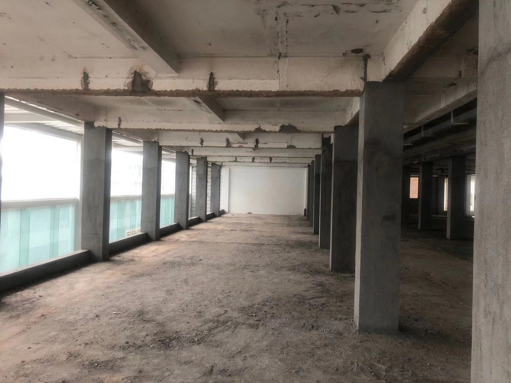
Pre-construction site condition (November 2020): An unfinished floor in the creative park, with a dense structural column grid and a glass curtain wall on one side. Column spacing and floor height were key constraints on the acoustic design.
This was not a single recording studio, but an integrated audio production cluster in which each room had a different acoustic purpose. The Foley studio was designed to capture a wide range of natural sounds, including footsteps, clothing movement, object impacts, rain, and water. Because Foley material can have a broad frequency range, high dynamic range, and strong transients, the design combined substantial absorption with controlled diffusion to reduce room coloration while preserving detail. A dedicated Foley pit was also included, with separate floor zones finished in materials such as marble, wood flooring, and carpet to capture footsteps and object sounds with different textures. The recording studio was primarily intended for music and voice recording. Its balance of absorption, diffusion, and reflection was designed to achieve an appropriate reverberation time (RT60) and an even sound field, producing a sound that was clean without feeling lifeless. The recording studio control room was configured for 5.1.4-channel immersive monitoring: five horizontal channels, one subwoofer channel, and four overhead channels. Its acoustic priorities were monitoring accuracy, suppression of early reflections, and control of comb filtering and low-frequency standing waves. The small editing room was intended for post-production audio editing, with an emphasis on low background noise and accurate near-field monitoring to reduce listening fatigue during extended sessions. The final mix room was configured for 7.1.4 channels to support final mixing, combining wide dynamic-range reproduction with speech intelligibility while controlling low-frequency standing waves.
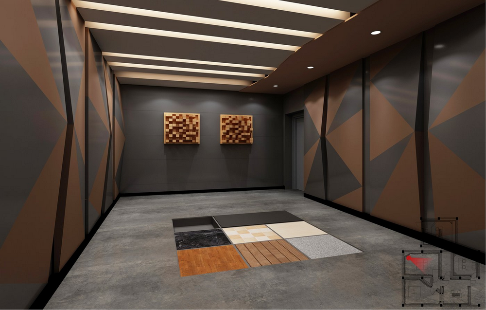
Foley studio design rendering: QRD diffusers and a Foley pit with separate floor-material zones (marble, wood flooring, carpet, etc.) for capturing different Foley sounds. (Design-stage rendering)
Because the five rooms were adjacent, sound isolation was a primary challenge. The design adopted a room-within-a-room approach using floating and decoupled structures. Resilient vibration-isolation layers were placed between the walls, floor, ceiling, and main building structure to interrupt structure-borne sound paths. Wall assemblies, acoustic doors, and windows were selected according to sound insulation ratings (Rw) so that the weakest element would not undermine the overall system—for example, a very thick wall paired with a poorly insulated door. The recording studio and Foley studio used geometrically shaped acoustic walls with triangular and diamond patterns to create non-parallel surfaces. These surfaces provided absorption while also diffusing sound, breaking up specular reflections and flutter echoes. The aim was to achieve consistent frequency response at different microphone positions while maintaining an attractive appearance.
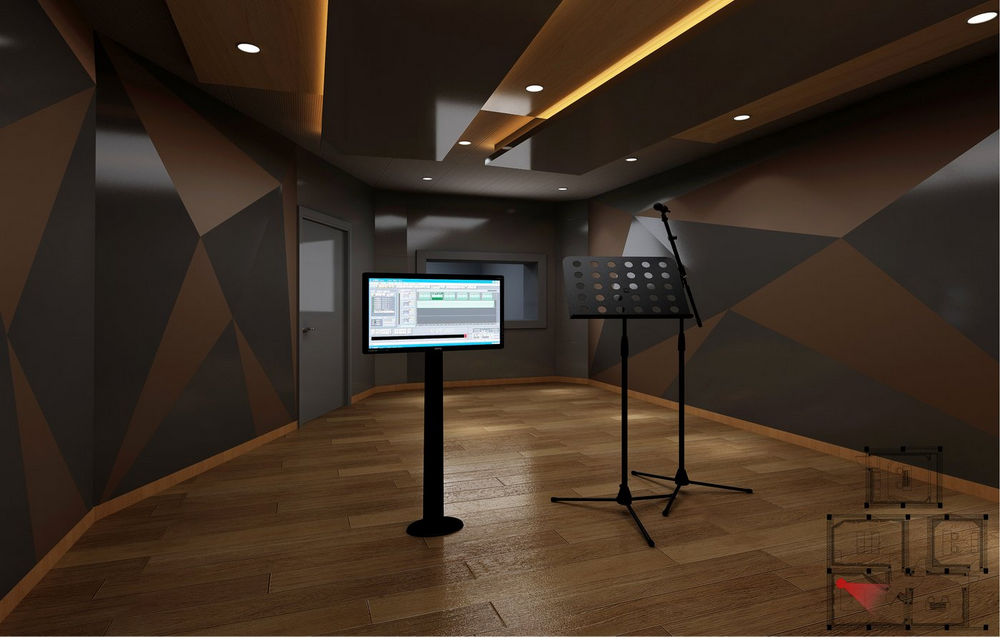
Recording studio design rendering: Geometric acoustic wall panels create non-parallel surfaces and combine sound absorption with diffusion. (Design-stage rendering)
An acoustic observation window was installed between the recording studio and control room. It used double or multiple layers of glass with sealed joints. The glass panes had different thicknesses to avoid overlapping resonance ranges, while the frame used resilient seals and was designed to match the sound insulation performance of the wall. This allowed clear visual communication and direction between the rooms without compromising sound isolation—the classic studio relationship of “see but do not hear.” The immersive-audio rooms, namely the control room and final mix room, also required particular attention to left-right symmetry. Absorption and diffusion treatments were arranged symmetrically around the room’s centerline, and loudspeakers were positioned at standard angles to ensure consistent monitoring response across channels. Otherwise, immersive sound localization and the spatial image could be distorted.
Around the start of construction, the project team completed five construction quality and technical briefings. The documents were issued under the project title “Recording Studio Acoustic Fit-Out Project” and covered: resilient/vinyl flooring installation (substrate moisture content below 3%; surface flatness checked with a 2 m straightedge, with gaps no greater than 2 mm; apply primer in both directions before self-leveling); engineered wood flooring installation (materials must have factory certificates and warranty documents; relative humidity in the work area controlled at around 60%; installation only after building-services lines have been laid and commissioned); installation of lighting, switches, and sockets (steel conduit wall thickness of at least 1.5 mm; galvanized supports selected according to luminaire weight); distribution board installation (adequate enclosure mechanical strength, a second-layer base plate at least 1.5 mm thick, and neatly arranged, securely terminated conductors); and door and window installation (incoming inspection of raw materials and finished products; witnessed sampling and testing for materials affecting safety performance; each subsequent process to begin only after the preceding one passes inspection; and inspection records to be completed before concealed work is covered).
Why these five work items? They correspond to three common sources of quality problems in recording studios. The floor is part of the recording environment: hollow or uneven flooring can create footstep vibration and shoe noise. Doors and windows are often the weakest links in the sound-isolation system: a poorly sealed door can compromise an entire sound-insulated wall. Electrical installation and grounding can be sources of hum: poor grounding may introduce persistent noise into an expensive recording signal chain. Technical requirements and acceptance criteria were therefore communicated before work began, so that every process had a clear standard.
Site photographs from March 2021 document the decision to install building services first. The fan-coil units had been suspended in place, while air-conditioning ducts and water pipes were routed below the beams. The sequencing principle for acoustic fit-outs is to complete building services before acoustic construction. The air-conditioning, fresh-air, fire-sprinkler, and cable-tray systems must be installed and pressure-tested before the acoustic ceilings and partition walls are closed. Otherwise, later drilling and pipe additions could damage the most sensitive sound-isolation and absorption assemblies. Sleeves were reserved wherever services passed through walls, and the surrounding gaps were filled with resilient sealant to prevent sound leakage. Although this stage may appear unrelated to acoustics, it determines whether the subsequent acoustic assemblies can remain intact.
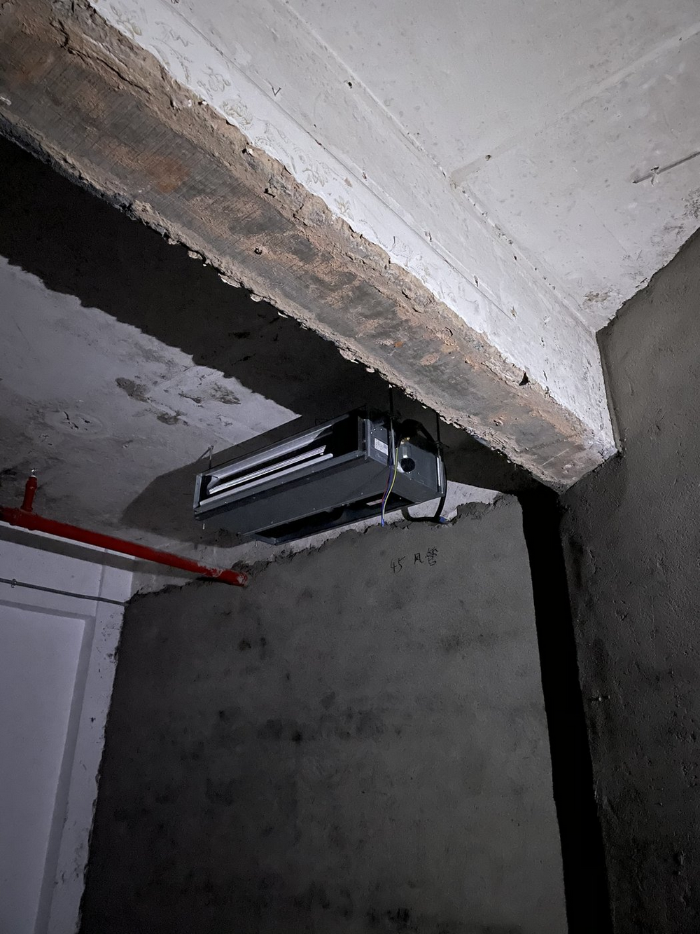
Building services installation (March 2021): Fan-coil units suspended in position. Mechanical and electrical services were installed first to make room for the acoustic ceilings and partition walls.
The project team officially entered the site on April 8, 2021. It developed and implemented specific measures for the three major challenges identified during the design stage.
Challenge analysis: The available room height was limited, restricting the space for acoustic assemblies. Sound-isolation and sound-absorption layers could add considerable thickness, making it difficult to meet both isolation and absorption targets. Acoustic defects such as low-frequency standing waves and flutter echoes could result.
Solution: Taking the available ceiling height into account, the team used acoustic simulation software to optimize the sound-isolation and absorption assemblies and selected high-performance, slim acoustic materials. The aim was to maximize acoustic performance within the limited space, making effective use of every centimeter of construction depth and ensuring that all five rooms met the project’s recording-studio acoustic requirements.
Challenge analysis: Air-conditioning services, fire-protection piping, and acoustic assemblies had to be integrated within a restricted ceiling void. Poorly planned service routes could cause physical conflicts, reduce the available thickness of acoustic assemblies, or transmit equipment noise into the rooms through rigid connections, right-angle bends, and elbows—compromising acoustic performance.
Solution: Before construction, the acoustic, HVAC, and fire-protection teams coordinated the service routes and installation positions. Services were routed to avoid acoustic assemblies, flexible connections were used to isolate equipment vibration, and every wall penetration was sealed. This allowed the building systems to be accommodated without compromising the acoustic construction. The site photograph below shows the ceiling framing and fire-protection pipes arranged in separate layers within the same restricted space, demonstrating how the coordinated layout was implemented.
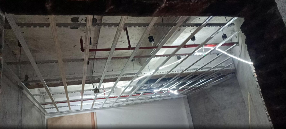
Construction photograph (April 2021): Coordinated arrangement of ceiling framing and fire-protection piping. HVAC, fire-protection, and acoustic systems were routed independently within the limited ceiling space.
Challenge analysis: The Foley pit was a specialized construction detail being implemented for the first time on this project, with no established in-house construction precedent. Its assembly involved separate floor finishes for different materials, sound absorption on the pit walls, and vibration isolation at the base. Both construction detailing and acoustic performance were difficult to control. Poor execution could affect the quality of Foley recordings and potentially create a path for noise transmission.
Solution: Before construction, the team reviewed established industry examples and refined the construction details. A specialist crew built a mock-up section, which was verified through acoustic testing before full-scale implementation. In other words, the team first built a section of the pit and collected test data, confirmed that both its function and acoustic performance met the requirements, and then applied the approved method to the remaining work.
The project team worked backward from the 55-day overall schedule. After entering the site on April 8, it first completed structural decoupling for sound isolation and substrate preparation. The partition framing for the five rooms, multilayer gypsum-board composite walls, and ceiling subframes were then constructed in parallel. The remaining work proceeded through acoustic finishes, the Foley pit, floor leveling and flooring installation, acoustic doors and windows, and final electrical fittings. The construction photographs below show a typical acoustic partition assembly: a composite timber and light-gauge steel frame with multiple layers of gypsum board installed with staggered joints. The wall was built layer by layer to match the required sound insulation rating, and resilient connections were also used at the ceiling-to-wall junction to prevent rigid sound transmission paths.
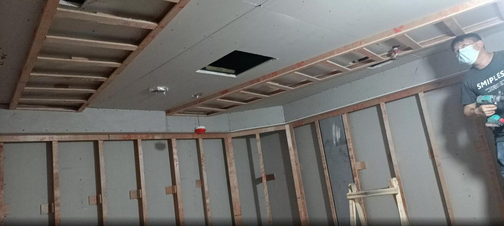
Construction photograph (April 2021): Acoustic partition framing and ceiling subframes installed concurrently, with work progressing in multiple rooms.
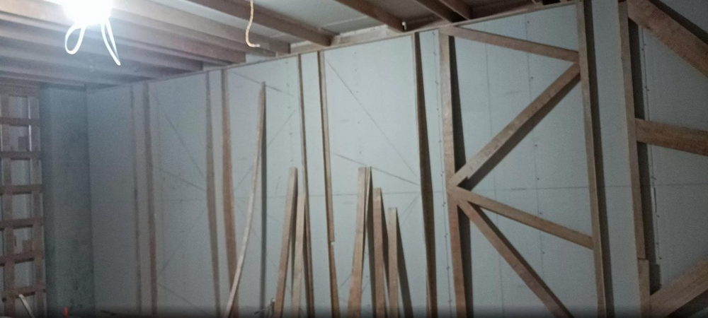
Construction photograph (April 2021): Multilayer gypsum-board composite sound-insulation wall, built layer by layer to meet the required sound insulation rating.
The project was completed on June 2, 2021, approximately 55 days after site mobilization. All five specialist acoustic rooms were completed in accordance with the design: the Foley studio, recording studio, recording studio control room, small editing room, and final mix room, each serving its intended purpose within the 150 m² workspace. Acoustic doors and windows, the observation window, Foley pit, geometric acoustic walls, and coordinated building-services details were all implemented. For accuracy, the project handover file did not retain photographs of the completed rooms after final acceptance. The images below are therefore design-stage renderings showing the intended appearance of each room; their captions clearly identify them as design-stage renderings, and they are not presented as photographs of the finished site.

Recording studio control room design rendering: 5.1.4-channel immersive monitoring, QRD diffusers, and an acoustic observation window. (Design-stage rendering)
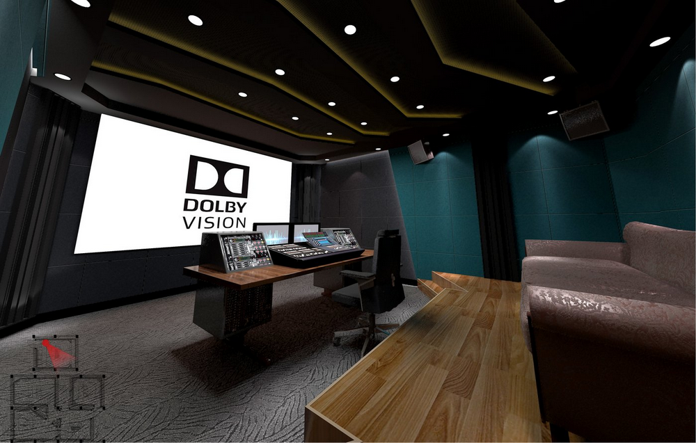
Final mix room design rendering: 7.1.4-channel immersive mixing environment with a large-screen review area. (Design-stage rendering)
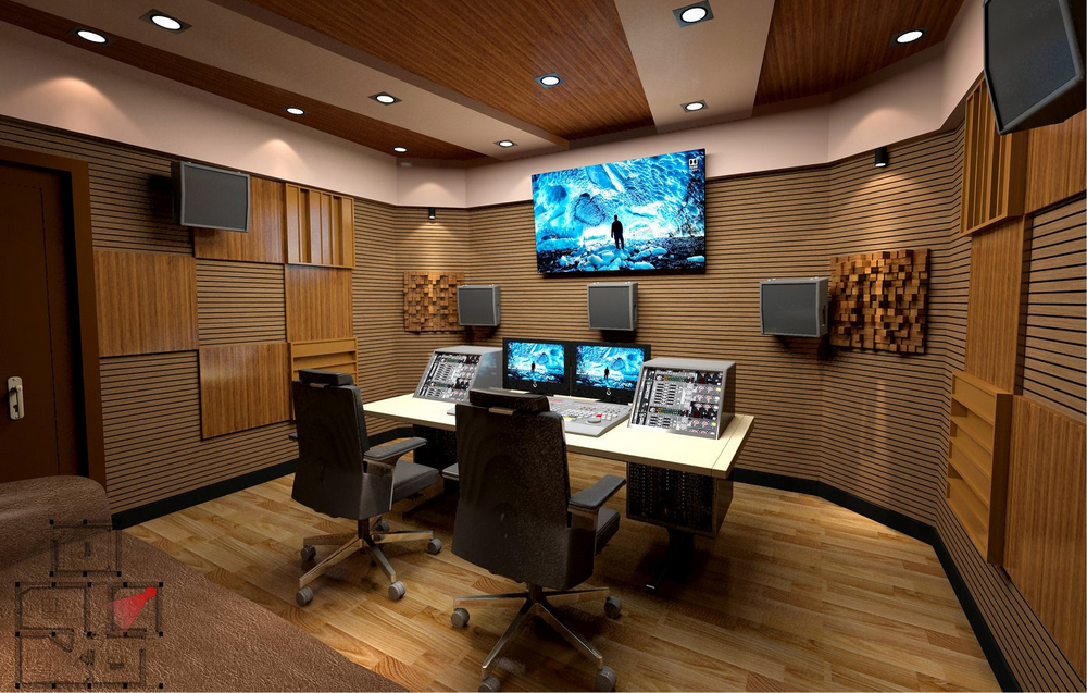
Small editing room design rendering: A post-production audio editing workstation combining slatted diffusion and sound-absorbing treatments. (Design-stage rendering)
Acceptance of the recording studio project focused on three principal acoustic indicators. Reverberation time (RT60) was to be measured in accordance with GY 5022-2007, Measurement Specification for Reverberation Time in Radio and Television Broadcasting/Performance Rooms, and GB/T 50076-2013, Measurement Specification for Reverberation Time in Rooms, and checked against the design values for each room. Sound insulation (Rw) involved checking consistency between the laboratory ratings of the walls, acoustic doors and windows, and observation window and the assemblies installed on site, with particular attention to sealing around frames and wall penetrations. Background noise (NR) was to be measured while equipment was operating, including checks on airflow velocity at air-conditioning outlets and the effectiveness of equipment vibration isolation. In addition to these three acoustic indicators, the electrical installation was to be inspected under GB 50303-2015, Code for Acceptance of Construction Quality of Building Electrical Engineering, and GB 50169-2016, Code for Construction and Acceptance of Grounding Connections in Electrical Installations, including grounding resistance and conductor termination quality. Visible fit-out quality was to be checked against GB 50210-2018, Standard for Quality Acceptance of Building Decoration and Fit-Out Works.
For the acceptance process, concealed work—including sound-isolation assemblies, service routing, and the Foley pit substrate—was to be submitted for inspection and documented before being covered. Each work section followed a handover inspection procedure: the next process could begin only after the preceding process had passed inspection. Both requirements were specified in the technical briefing for the door and window works. It should be noted that the project handover file did not retain a third-party acoustic test report. Actual measured values should therefore be confirmed from the final acceptance records; no values have been assumed or added in this case study.
For ongoing maintenance, it is recommended that the seals and hardware of acoustic doors and windows, as well as the seals around the observation window, be inspected regularly. Acoustic finishes should be protected from impact and moisture. Silencing components in air-conditioning outlets should be cleaned periodically. The multichannel monitoring systems in the control room and final mix room should ideally be calibrated and measured once a year to help maintain the rooms’ acoustic condition at the level achieved at handover.
A: The schedule depends on the number of rooms and the required acoustic performance. In this project, five specialist acoustic rooms—a Foley studio, recording studio, control room, small editing room, and final mix room—were delivered within a 150 m² area in approximately 55 days from site mobilization to completion. Key schedule factors include handover of the base-building works, construction and curing of sound-isolation structures, installation of acoustic finishes, the lead time for custom acoustic doors and windows, and acoustic calibration and system integration for multichannel audio. Sufficient time should be reserved for acoustic acceptance testing and commissioning.
A: The two spaces serve different purposes. A Foley studio is designed to capture natural sounds, which may have a wide frequency range, high dynamic range, and strong transients. Its design therefore emphasizes low background noise and substantial sound absorption to reduce room coloration and preserve detail. It often includes a Foley pit with different floor materials. A recording studio is mainly used for music and voice and relies on a carefully balanced combination of absorption, diffusion, and reflection to control reverberation time while retaining clarity and a natural sense of space. Although the two rooms may be used together, their absorption levels, diffuser layouts, and performance targets differ; the same design should not simply be applied to both.
A: In the X.Y.Z format, the numbers represent the number of horizontal-layer channels, low-frequency effects (LFE) channels, and overhead (height-layer) channels, respectively. A 5.1.4 system has five horizontal channels, one subwoofer channel, and four overhead channels. A 7.1.4 system adds two side/rear surround channels, providing more complete horizontal envelopment. Both require the same acoustic fundamentals: low background noise, symmetrical room construction, and consistent monitoring response across channels. Otherwise, immersive sound localization and spatial imaging may be distorted.
A: A room-within-a-room structure creates an independent inner shell inside the original building room, using resilient vibration-isolation layers, independent walls, and an independent ceiling to decouple it from the main structure. This reduces both airborne and structure-borne sound transmission and is a high-performance approach to controlling background noise in recording rooms located in urban buildings. An acoustic observation window uses double or multiple glazing with sealed joints to allow the studio and control room to work together visually while maintaining sound isolation. The window frame’s sound insulation rating must match that of the wall; otherwise, a single window can undermine the isolation performance of the entire wall.
A: The key is to combine structural decoupling, airtight sealing, and performance matching. Decoupling: install resilient vibration-isolation layers between the walls, floor, ceiling, and main building structure to interrupt structure-borne sound. Sealing: seal door and window gaps, wall penetrations, and service sleeves to prevent sound leakage. Matching: ensure that the sound insulation rating of acoustic doors and windows is compatible with that of the walls, avoiding a weakest-link effect. All three are essential; a failure in any one of them can compromise the overall sound isolation.
A: Acceptance typically focuses on three indicators: reverberation time (RT60), sound insulation (Rw), and background noise (NR), with testing carried out in accordance with standards such as GY 5022-2007 and GB/T 50076-2013. Concealed works and individual work sections should be documented and inspected through a formal handover process. The third-party test report was not retained in this project’s handover file, so actual acceptance should be based on the indicators and testing methods agreed by the parties. For maintenance, regularly inspect acoustic door and window seals, acoustic finishes, and air-conditioning silencing components, and periodically calibrate the multichannel monitoring system.
A: Four points deserve particular attention: whether the contractor has completed comparable multi-room recording studio projects, with design, construction, and acceptance delivered as an integrated service rather than as isolated work packages; whether it is familiar with recording studio acoustic standards such as GY/T 5086 and the relevant measurement procedures; whether it has its own construction teams and a robust technical briefing system—much of the quality of a recording studio project depends on concealed work; and whether it can provide acoustic testing and after-sales maintenance. An unusually low price may indicate non-standard sound-absorbing materials, assemblies that have not been acoustically calculated, or handover without testing. A recording studio is a room built to serve sound, and the cost of rework can far exceed the original fit-out cost.
Misconception 1: Acoustic treatment simply means covering the recording studio with sound-absorbing foam.
A: Excessive absorption can make sound dull and remove its sense of space. A professional design balances absorption, diffusion, and reflection according to the function of each room, and verifies the result against indicators such as reverberation time. The “dry” sound desired in a Foley studio and the “warm” sound desired in a recording studio require different treatment balances. Every layer of a wall, from the framing to the finish, is selected to address particular frequency ranges.
Misconception 2: Treat only the walls and ceiling, and ignore doors, windows, and openings.
A: Weak points in sound isolation are often found around doors, windows, and wall penetrations. A single sound leak can significantly reduce overall sound insulation. Sealing and structural decoupling are equally important: socket back boxes, service sleeves, and air-conditioning outlets must all be properly sealed. Any overlooked detail may become apparent during sound-isolation acceptance testing.
Misconception 3: Small rooms do not need sound isolation because problems can be fixed in post-production.
A: Background noise and room coloration are physical problems that are difficult to repair with post-production software. Once noise has been recorded, it remains in the audio. Foley and recording studios depend particularly on a clean acoustic foundation. Smaller rooms actually require more careful attention to room proportions and more precise low-frequency treatment.
Misconception 4: 5.1.4 and 7.1.4 simply mean buying a few more loudspeakers.
A: Immersive audio depends on consistent room acoustics and symmetrical construction. If absorption and diffusion on the left and right walls are unbalanced, or loudspeakers are positioned arbitrarily, frequency response will vary between channels and localization and spatial imaging will be distorted. No matter how good the equipment is, it cannot perform properly under these conditions. System calibration and acoustic measurements are also required after construction before a room can truly support immersive monitoring.
Misconception 5: HVAC, fire protection, and other building services are unrelated to acoustics and can be installed independently.
A: This project identified conflicts between multiple building systems as a major construction challenge. Services can reduce the available thickness of acoustic assemblies, right-angle bends can transmit equipment noise, and drilling after completion can damage sound-isolation layers. These are typical consequences of poor coordination between building services and acoustic construction. The correct approach is to coordinate service routes across disciplines before construction, install building services first and acoustic assemblies afterward, and provide sealed sleeves at all wall penetrations.
Misconception 6: Any contractor with general fit-out qualifications can build a recording studio.
A: Qualifications are the entry requirement; experience is what matters. The key differentiators are whether the contractor has delivered comparable multi-room studio clusters, understands recording studio acoustic standards and measurement procedures, and has experience with specialized construction details such as Foley pits. The cost of trial and error in acoustic engineering is high. Choosing a contractor is ultimately about choosing proven experience.
The principal standards relevant to the design, construction, and acceptance of this project are listed below:
Category | Standard No. | Standard Title |
Recording Studio Acoustic Design | GY/T 5086-2012 | Acoustic Design Code for Radio and Television Recording (Broadcast) Rooms and Studios |
Reverberation Time Measurement | GY 5022-2007 | Measurement Specification for Reverberation Time in Radio and Television Broadcasting/Performance Rooms |
Acoustic Construction and Acceptance | GY/T 5087-2012 | Code for Construction and Acceptance of Acoustic Fit-Out Works in Radio and Television Centers |
Auditorium Acoustics | GB/T 50356-2005 | Acoustic Design Code for Theaters, Cinemas, and Multipurpose Auditoriums |
Building Sound Insulation | GB 50118-2010 | Code for Design of Sound Insulation in Civil Buildings |
Reverberation Measurement | GB/T 50076-2013 | Measurement Specification for Reverberation Time in Rooms |
Sound Reinforcement Design | GB 50371-2006 | Code for Design of Sound Reinforcement Systems in Auditoriums |
Fit-Out Acceptance | GB 50210-2018 | Standard for Quality Acceptance of Building Decoration and Fit-Out Works |
Electrical Installation | GB 50303-2015 | Code for Acceptance of Construction Quality of Building Electrical Engineering |
Grounding Systems | GB 50169-2016 | Code for Construction and Acceptance of Grounding Connections in Electrical Installations |
Fire Protection Design | GB 50016-2014 (2018 Edition) | Code for Fire Protection Design of Buildings |
Guangzhou Saijia Acoustic & Lighting Engineering Co., Ltd. undertakes acoustic fit-out and integrated audio, lighting, and electrical system projects in China and overseas, including recording studios, Foley studios, voice-over booths, podcast rooms, livestreaming rooms, XR studios, converged media centers, theaters, and multipurpose halls. The company primarily serves South China, East China, Central China, and Southwest China, with particular experience in projects across the Greater Bay Area and Pearl River Delta. From acoustic design, sound and vibration isolation, and room-acoustic treatment to acoustic fit-out construction and acceptance, it provides end-to-end project delivery and responsive local support.
Guangzhou Saijia Acoustic & Lighting Engineering Co., Ltd. | Tel: +86 20 8629 9208 | Address: Room 615, Building 3, No. 135 Huangyuan Road, Baiyun District, Guangzhou, China